
Abstract: This project implements idea of automatic railway gate. A microprocessor is used to implement logic. A sensor is used to detect arrival of a train. In normal conditions, Traffic light is green, Seven Segment is showing 0. Motor is at stationary position. When a train is approaching, it will turn on green light, motor will rotate to off the gate and seven segment will start showing count down.
Motivation:
Railway crossing are
all over the Pakistan and most of them are manual They causes a lot of trouble
and accidents have become common. Also govt. have to spend a lot of money on servants
too. Also there are a lot of railway crossing without gates. The purpose of
this project is to present a way to make the automatic to overcome these
problems.
High Level
Design
Background:
This is a open loop system where input is being fetched to the
system with sensors and then accordingly motor is being derived and output is
being shown.

A pressure sensor will be implemented on both side of railway gate
at a appropriate distance that will give a signal to microcontroller that will
command a motor controller ic to rum a motor and also a red traffic signal to
on. When train will reach other side of the gate, another sensor will input
microcontroller to open the gate and change the light to green.

Figure 1
Logical Construction:

Hardware/Software
Design
1) Motor Driver
This is half bridge motor driver IC
that controls DC motor direction with 2 inputs and that can rotate motor clock
and anti clock wise. Below is a picture of half bridge. This allows to apply
voltage in either direction to move motor forward or backward direction.

Figure 2
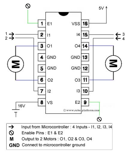
We uses LM293D motor driver IC which
has this circuit embedded in it. It can control 2 motors and can provide a
current of 600 mA. Pin configuration are as follows.
Figure 3

L293D Circuit:
The circuit shown to the right is the most
basic implementation of L293D IC.
Driver using Arduino:
Simulation:
 Flow Chart:


Code:
/* Author: Muhammad Awais Program Name: Motor Driver Descrption: It is minimal Motro driver program that rotates motor in clock and anti clock wise. */ #define MotorInput1 2 #define MotorInput2 3 // the setup function runs once when you press reset or power the board void setup() { // initialize digital pins as an output. pinMode(MotorInput1, OUTPUT); pinMode(MotorInput2, OUTPUT); } // the loop function runs over and over again forever void loop() { MotorDriver(1); delay(1000); // wait for a second MotorDriver(0); delay(1000); }/* Descrption: This function is used to drive motor clock or anticlok wise as needed. It will be used with L293D IC. Input: bool, 1 for clockwise and 0 for anticlock wise Output: It makes pins relative IC pins 1 and zero accordingly */ void MotorDriver(bool Direction) { if (Direction==1) { digitalWrite(MotorInput1, 1); // turn the LED on (HIGH is the voltage level) digitalWrite(MotorInput2, 0); // turn the LED off by making the voltage LOW delay(300); digitalWrite(MotorInput1, 0); // turn the LED on (HIGH is the voltage level) digitalWrite(MotorInput2, 0); // turn the LED off by making the voltage LOW } else if(Direction==0) { digitalWrite(MotorInput1, 0); // turn the LED on (HIGH is the voltage level) digitalWrite(MotorInput2, 1); // turn the LED off by making the voltage LOW delay(300); digitalWrite(MotorInput1, 0); // turn the LED on (HIGH is the voltage level) digitalWrite(MotorInput2, 0); // turn the LED off by making the voltage LOW } }
IR Sensors:
Infrared Sensors are used to detect arrival of
train. Infrared sensor comprises of a transmitter and a receiver. Transmitter is a LED that
transmits infrared light at given frequency and receiver receives it. It is
used for communication by PWM but as we only need to detect train arrival so we
are using it to send 1 for not arrival and 0 for arrival. So transmitter will
continue sending light to receiver but when train will arrive, it will send 0.
So we can detect arrival of train.
In this sensor circuit, we will use a Op-Amp. This
will be used to make analog input to digital output so that we can see arrival
of train as 0 and not arrival as 1. Otherwise this sensor produces analog
values based on incoming waveform. We will be using LM324 IC which contains
four op amps but we are here only one is used. Following is IC information.


We used Op-Amp in comparator mod. The output of the comparator is high if voltage at positive end is more than voltage at negative end and gives low output if voltage at positive end is lesser than negative end.

Sensor Simulation:
As IR sensor is not available in
simulation so we are simulating it with a switch. When switch will be on, it
will be simulating as train arrival and Open will be simulating departure form
the location. Then amplifier is converting these values to zero and one
accordingly.


This is hardware design of the
sensors. Two sensor with 12cm distance are installed. 12cm is for train
passing.


Display:
As soon as sensor will detect train
arrival, the red light will be on showing gate closure and Seven Segment will
be showing S. When train will be passed, seven segment will show O for open and
light will turn into green. Also our controller will communicate with central
train system and will give them present situation of the gate.
A seven segment is used to show traffic
remaining time. A seven segment is simply 7 led containing box which can show
numbers from 0 to 9.

To program it, we should know what
led to on and what to off. So here is a list where we can see how to led on or
off corresponding to each number.

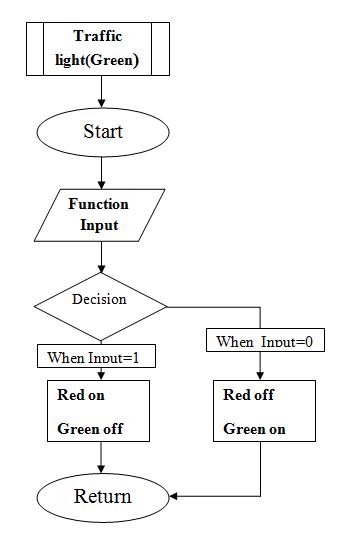
Flow Chart:
This function is used to turn light on or off accordingly.
For Count down timer. This function shows reaming time on seven segment

This function is used to communicate with external UART device.

Code:
/* Descrption: This function have two things to do.On red with off green or, off red with on Gree. If input is 1,RED will be on and Green will be off If input is 0,Green will be on and Red will be off Input: State, 1 or ) only Output: Makes Light on and off accordingly */ void trafficLight(int state) { if (state==1) { digitalWrite(Red,1); digitalWrite(Green,0); } else if (state==0) { digitalWrite(Red,0); digitalWrite(Green,1); } } /* Descrption: It serially communicates with any device attached and tell the train situation. Input: Train state Output: Serially communicates state of train. */ void Communication(int state) { if (state==1) { Serial.println("Train is approaching at Railway Crossing Number: 25"); } else if (state==0) { Serial.println("NO Train at Railway Crossing Nubmer: 25"); } }/* Descrption: It is for Seven segment display.Starts form 9, it deceremtns counter each second. As soon as it is called, it will start counting down. Input: No input Output: */ void CountDownTimer() { SevenSegOff(); // write '9' digitalWrite(A, 1); digitalWrite(B, 1); digitalWrite(C, 1); digitalWrite(D, 0); digitalWrite(E, 0); digitalWrite(F, 1); digitalWrite(G, 1); delay(1000); // write '8' digitalWrite(A, 1); digitalWrite(B, 1); digitalWrite(C, 1); digitalWrite(D, 1); digitalWrite(E, 1); digitalWrite(F, 1); digitalWrite(G, 1); delay(1000); // write '7' digitalWrite(A, 1); digitalWrite(B, 1); digitalWrite(C, 1); digitalWrite(D, 0); digitalWrite(E, 0); digitalWrite(F, 0); digitalWrite(G, 0); delay(1000); // write '6' digitalWrite(A, 1); digitalWrite(B, 0); digitalWrite(C, 1); digitalWrite(D, 1); digitalWrite(E, 1); digitalWrite(F, 1); digitalWrite(G, 1); delay(1000); // write '5' digitalWrite(A, 1); digitalWrite(B, 0); digitalWrite(C, 1); digitalWrite(D, 1); digitalWrite(E, 0); digitalWrite(F, 1); digitalWrite(G, 1); delay(1000); // write '4' digitalWrite(A, 0); digitalWrite(B, 1); digitalWrite(C, 1); digitalWrite(D, 0); digitalWrite(E, 0); digitalWrite(F, 1); digitalWrite(G, 1); delay(1000); // write '3' digitalWrite(A, 1); digitalWrite(B, 1); digitalWrite(C, 1); digitalWrite(D, 1); digitalWrite(E, 0); digitalWrite(F, 0); digitalWrite(G, 1); delay(1000); // write '2' digitalWrite(A, 1); digitalWrite(B, 1); digitalWrite(C, 0); digitalWrite(D, 1); digitalWrite(E, 1); digitalWrite(F, 0); digitalWrite(G, 1); delay(1000); // write '1' digitalWrite(A, 0); digitalWrite(B, 1); digitalWrite(C, 1); digitalWrite(D, 0); digitalWrite(E, 0); digitalWrite(F, 0); digitalWrite(G, 0); delay(1000); // write '0' digitalWrite(A, 1); digitalWrite(B, 1); digitalWrite(C, 1); digitalWrite(D, 1); digitalWrite(E, 1); digitalWrite(F, 1); digitalWrite(G, 0); }void SevenSeg0() { digitalWrite(A, 1); digitalWrite(B, 1); digitalWrite(C, 1); digitalWrite(D, 1); digitalWrite(E, 1); digitalWrite(F, 1); digitalWrite(G, 0); }
/*
Descrption: To off Seven Segment
*/
void SevenSegOff()
{
digitalWrite(A, 0);
 digitalWrite(B, 0);
 digitalWrite(C, 0);
 digitalWrite(D, 0);
 digitalWrite(E, 0);
 digitalWrite(F, 0);
 digitalWrite(G, 0);
}
Simulation:
When no Train is
arriving


Serial
Communication:


When Train is
Arriving:


Serial
Communication:


Complete System
Hardware:
Simulated Hardware:
This is complete circuit design on simulation.
1) When Train is approaching.


2) When NO train


Software:
Following flow chart describes the whole software.
Code:
#define MotorInput1 3
#define MotorInput2 4
int Sensor = 2;
int Red=A0;
int Green=A1;
int A=12;
int B=11;
int C=10;
int D=9;
int E=8;
int F=7;
int G=6;

void setup() {
  // initialize serial communication at 9600 bits per second:
  Serial.begin(9600);
//Initilize pins for sensor, traffic lights and seven Segment
  pinMode(Sensor, INPUT);
  pinMode(Red,OUTPUT);
  pinMode(Green,OUTPUT);
  pinMode(A, OUTPUT);
  pinMode(B, OUTPUT);
  pinMode(C, OUTPUT);
  pinMode(D, OUTPUT);
  pinMode(E, OUTPUT);
  pinMode(F,OUTPUT);
  pinMode(G, OUTPUT);
  //For motor
  pinMode(MotorInput1, OUTPUT);
  pinMode(MotorInput2, OUTPUT);


}
// Main program
void loop() {
  // read the Sensor
  int Train = digitalRead(Sensor);
  delay(1);        // delay in between reads for stability

  //When train is approaching
  if(Train==1)
  {
   trafFcLight(Train);
   MotorDriver(1);
   Communication(Train);
   CountDownTimer();
   MotorDriver(0);

  }

  //When No train
  else if(Train==0)
  {
   trafFcLight(Train);
    SevenSeg0();
   Communication(Train);
   }
}
Excellent work dear thanks for this
ReplyDeleteUetian Blogger: Automatic Railway Crossing >>>>> Download Now
Delete>>>>> Download Full
Uetian Blogger: Automatic Railway Crossing >>>>> Download LINK
>>>>> Download Now
Uetian Blogger: Automatic Railway Crossing >>>>> Download Full
>>>>> Download LINK Er
Great Blog, there is so much reality written in this content and everything is something which is very hard to be argued. Top notch blog having excellent content.
ReplyDeleteAutomatic Gate
Can you share circuit with circuit elements named in it.
DeleteUetian Blogger: Automatic Railway Crossing >>>>> Download Now
ReplyDelete>>>>> Download Full
Uetian Blogger: Automatic Railway Crossing >>>>> Download LINK
>>>>> Download Now
Uetian Blogger: Automatic Railway Crossing >>>>> Download Full
>>>>> Download LINK
Nice article I was really impressed by seeing this blog, it was very interesting and it is very useful for me. Informative blog! It was very useful for me. We are the Top Mobile App Development Company in India.
ReplyDeleteAlso Visits
Best Android App Developers
Best Android app development company
Elevate your digital presence with CMOLDS, the premier mobile app development company in UAE. With a focus on innovation and cutting-edge technology, we specialize in crafting bespoke mobile solutions tailored to your business needs. Partner with us to transform your ideas into powerful mobile experiences that drive success in the ever-evolving digital landscape.
ReplyDeleteTechlancers Middle East is a premier software development company dubai, dedicated to delivering customized software solutions that drive innovation and efficiency. Our expert team leverages the latest technologies to create scalable applications tailored to meet the unique needs of businesses in a competitive market.
ReplyDelete