CW multiplier is basically consists of n stages of a voltage doubler. A n stages CW converts Vpp (peak to peak) source voltage into n*Vpp or 2*n*Vp. Using only diodes and capacitors and cascading basic block, we can convert small AC voltage into high DC voltage. So a N stage CW voltage multiplier converts input with following way.

First of all let's analyse it fundamental building block to understand how it works.
 Here source is connected to a capacitor and a diode in parallel with reverse bias condition then there is another diode in forward bias configuration and then there is another capacitor. This Circuit Works in a following way.
In fist cycle of the input, _Vp, Capacitor C1 is fully charged with diode D1. Then in positive cycle this capacitor charged up to 2Vp. Then capacitor C5 charged with diode D2 up to 2*Vmax and in next stage whole cycle repeated it self.


First of all let's analyse it fundamental building block to understand how it works.

Design of 100 kV CW with 10 kV source and 10 mA load current
Now to multiply voltage by factor of 10 we have to cascade this fundamental circuit into 5 stages this way we will get 100kV with 2*5*10kV.
So number of stages =5
Second important thing here is capacitor values and rating. Voltage drop formula for this circuit is as follows

Now this formula describes that for a n stage cascaded CW multiplier, with frequency f and load current of I with C capacitance will have voltage drop of Delta V across output. From here we can find value of capacitance for our circuit by assuming a fair value of voltage tolerance. This C also effects time constant and ripples in this multiplier. So we are supposing a
del V=1V
f=50Hz
I=10mA
So capacitance value for this case would be 20mF capacitor.
Now we need to calculate ripple in this circuit. Formula for ripple calculation would be
So in our case ripple voltage would be .15% of total voltage.
Rating of the capacitors and diodes are one important parameter. As all the capacitors are stressed with 2Vmax of their stage so Capcitor and diode rating should be greater that 2Vmax of that stage which means second stage will have rating of 20kV, third will have 40 kV and it goes this way.
Proteus Simulation:

So following is a five stage voltage multiplier circuit.
All the stages are labelled. Highest stage is labeled as V1 and V1'. Working of this circuit is resembled to fundamental block with a difference that when charged V5' is charged up-to 2*V max in next cycle it charges c2 and so on and so for. Vn' are points where voltage will oscillate while on Vn voltage will be constant eventually.
Following are different graphs for as described.
Output Voltage vs Source Voltage :
 |
| Output Voltage vs Input Voltage: Output V eventually constant |
Load Current:
 |
| Load Current curve initially have some ripples which eventually becomes zeros at the end |
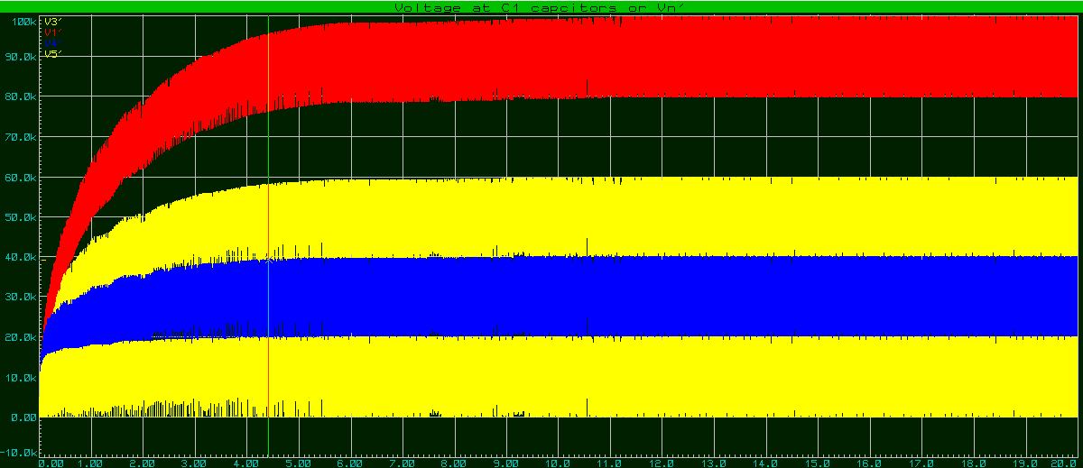
Voltages at V n' points:
Voltages are very oscillating but are double in each stage.
Voltages at V n points:
 |
| Voltages at Vn points. They have less ripples at quite stable. Also they are double on each stage |
With High load
As circuit is designed for smaller currents (load), so for higher loads voltage drop will increase tremendously. One such example is given following with a load of 100ohm inspite of 10M
Download Simulation:
Password of rar file is UETianBLogger